Calculating a polygon mesh in PostGIS
Note: I really don’t know how this kind of noded “network” of polygon-borders-as-lines is called in English, but I’ll refer to them as a “meshed up polygons”. Most probably because it sounds like messed up if you don’t get your pronunciation right. Maybe it’s correct, maybe not. If you happen to know, I’d be really glad if you let me know :)
Anyway. The story goes like this.
Introduction
Estonia has a relatively long coastline compared to it’s size ( ~3800 km vs 45K sq km), in addition a ton of smaller islands, and a couple of bigger lakes, so when it comes to vector data of administrative boundaries these will have quite some nodes. I guess the situation is even worse for other Nordic countries or really any other sea-side country, but that’s not what this writeup is about…
A few weeks ago I stumbled upon a case where we needed the lowest level administrative unit borders to be rendered as vectors on an OpenLayers powered webmap and those hundreds of thousands of nodes started to pose a real performance issue. One possibility to overcome this would have been to simplify the polygons, and maybe lose some territorial integrity, but that was deemed not possible because it was the “as-exact-as-can-be” land borders that we were really interested in.
In sudden stroke of an idea - what if we used “unique” inland boundaries instead, so that two neighboring areas are represented as a single-part linestring, and dropped the coastline border altogether? A pretty common technique used in chartography, so nothing novel actually. But thinking back, I had not done this kind of processing myself before.
For that to happen we’d have to do two things:
- node (or mesh up) the admin unit polygons
- add two additional attributes two all noded linestrings denoting the admin unit id to the left and to the right of the vector. Something that’s usually done in topological datasets (e.g routing networks).
Data
The A1-A3 level admin unit boundaries for Estonia can be downloaded in
various formats from the Estonian Land Board’s
homepage.
For this work I was using the A3 admin level
settlement borders
in shp format (i.e Asustusüksus SHP).
The zipped shapefile attribute data has the cp1257 codepage and the spatial
data is in the local national coordinate reference system
L-EST'97 (EPSG:3301).
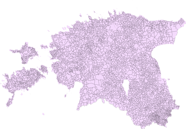
As of May 2018 Estonia has 4711 A3-level admin units and in their plainest,
simplest view they look like this:
After importing the settlements' areas data to a PostGIS database, the rest of the data processing was conducted there.
Processing
The data processing was divided into a series of steps consisting of
- polygons to linestings, removing duplicate borders
- merging all linestrings into a fully noded layer, forming a “mesh”
- and calculating sidedness - add left and right side A3-level unit identifiers to linestrings.
Most of this processing can be squeezed together into single statements but I’ll try to chop it up into smaller chunks results of which can be marvelled at in your favorite desktop GIS aswell.
Step 1.
First off we’ll dump all polygon rings and select their outer shells. There’s no
point in keeping the identifiers (akood, okood, mkood for A3, A2 and A1
admin levels respectively) because the geometries will be merged at some later
point anyway and lost.
drop table if exists ay_aslines;

create table ay_aslines as
select st_exteriorring((st_dumprings(shape)).geom) as geom
from asustusyksus;
This query is using a combination of st_dumprings and st_exteriorring in order to extract all rings that the polygons have (including holes, islands within those holes, and holes within those islands within the first holes, etc).
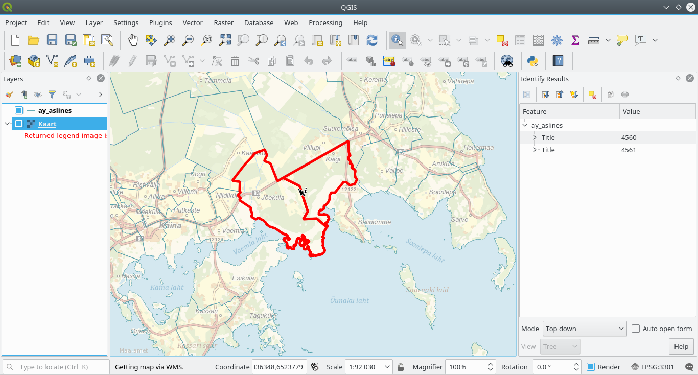
These resulting lines are all singlepart:
select distinct geometrytype(geom) from ay_aslines;


geometrytype
--------------------------------------------------------------------------------
LINESTRING
But we still have a layer of lines that share space - two neighboring admin-units each have their separate borders:
To make them non-repeating, we’ll aggregate all of them together with st_union (which might take a while depending on the dataset and the processing power of the database) and use st_dump to get a whole bunch of very short (2-node) linestrings:
The query for this operation is
drop table if exists ay_lines_merged;

create table ay_lines_merged as
select (st_dump(st_union(geom))).geom
from ay_aslines;
Step 2.
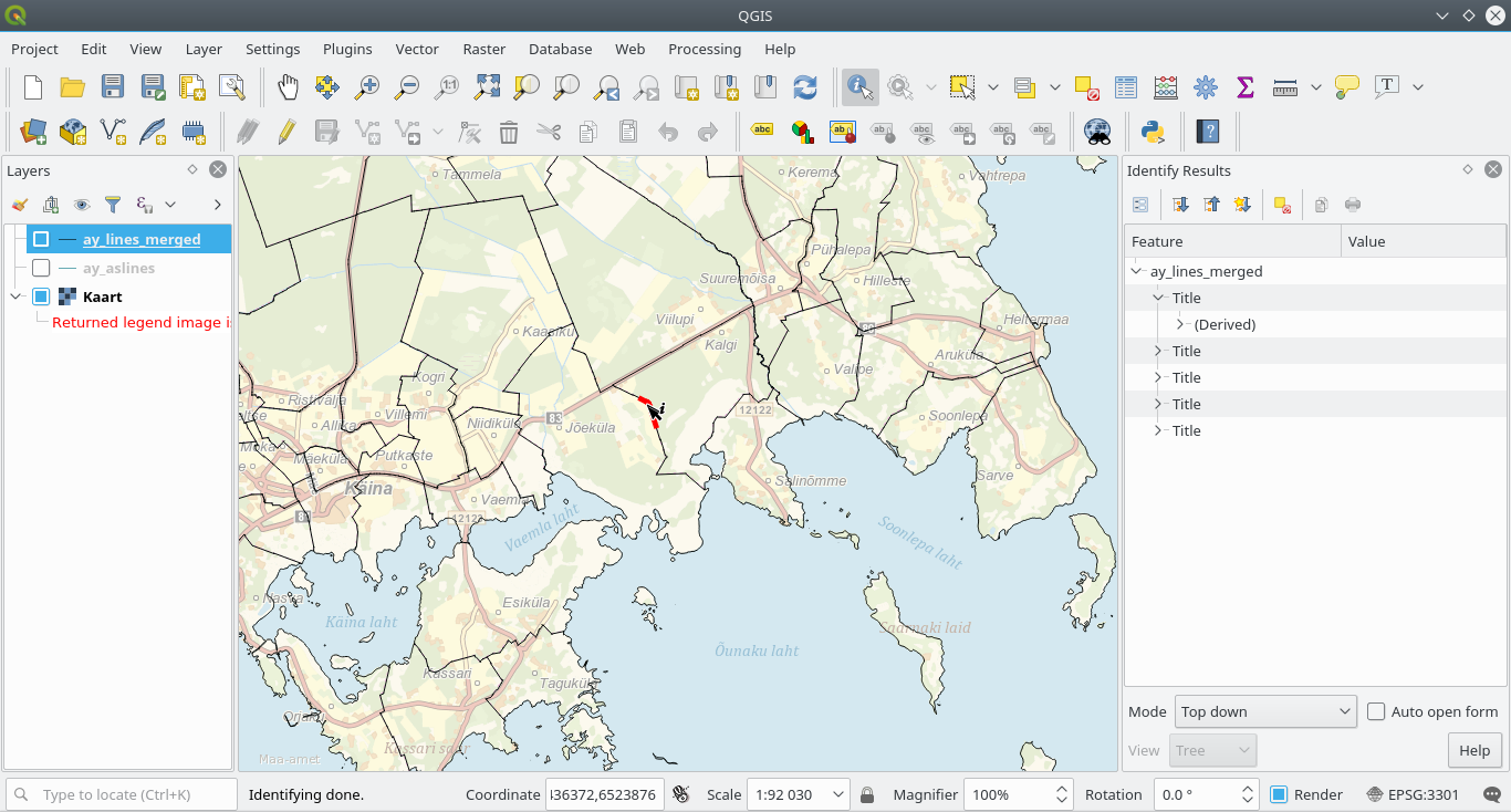
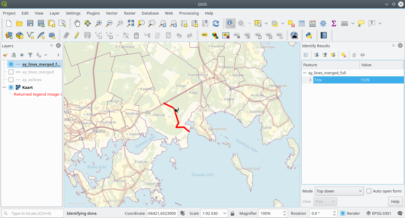
Now we’ll use st_linemerge to sow these linestrings together, seeding it with a multilinestring of all lines created with st_collect, and again st_dump them to singlepart linestrings that are now properly noded - you can think of this as a road network with all the roads split at intersections.
drop table if exists ay_lines_merged_full;

create table ay_lines_merged_full as
select
    path[1] as id, geom
from (
    select (st_dump(st_linemerge(st_collect(geom)))).*
    from ay_lines_merged
) foo;
and voilà:
Step 3.
If we were only interested in a mesh of line geometries then the task would be complete, but what we’re really after is finding those borders that are not shared between two adjacent administrative units. Basically filtering out those that have coastline (or country border on the land) on one side and an admin unit on the other. Therefore we still need to calculate sidedness information.
This can be achieved for example by shifting the noded linestrings left and right by a ridiculously small distance using st_offsetcurve, finding a midpoint of the shifted line with st_lineinterpolatepoint and then simply querying then admin unit that this midpoint is within with st_within. The “ridiculously small distance” mentioned earlier is 0.01 meters. This distance needs to be kept at a minimum because otherwise the point geometry we construct from it afterwards might end up in a completely wrong place. Also note the use of st_dump again as offsetting self-touching linestrings (for example: islands) left/right can create self-intersecting lines and therefore multitype geometries or other oddities.
drop table if exists ay_lines_shift_left;
create table ay_lines_shift_left as
select id, (st_dump(st_offsetcurve(geom, 0.01))).geom as geom
from ay_lines_merged_full;
drop table if exists ay_lines_shift_right;
create table ay_lines_shift_right as
select id, (st_dump(st_offsetcurve(geom, -0.01))).geom as geom
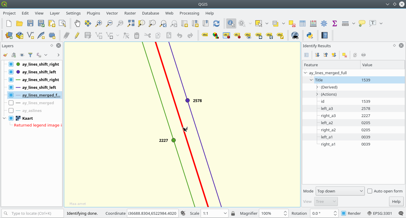
from ay_lines_merged_full;If the map is zoomed really close these shifted lines can be distinguished
Next up, add columns to hold the geometry of the midpoints to the shifted lines table
alter table ay_lines_shift_left add column midpoint geometry(Point, 3301);
alter table ay_lines_shift_right add column midpoint geometry(Point, 3301);
Calculate midpoint values based on st_lineinterpolatepoint. This is the preferred way to, for example using st_centroid which can have inadvertent consequences. A centroid of the geometry is not guaranteed to intersect the geometry it represents, it’s just a “center of mass of the geometry”
update ay_lines_shift_left set
    midpoint = st_lineinterpolatepoint(geom, 0.5);

update ay_lines_shift_right set
    midpoint = st_lineinterpolatepoint(geom, 0.5);
And now simply create the appropriate left/right columns to be populated.
alter table ay_lines_shift_left add column a3_id varchar(4);
alter table ay_lines_shift_right add column a3_id varchar(4);
Add some indexes to make the queries run a bit faster
create index sidx__ay_lines_shift_left__midpoint
    on ay_lines_shift_left using gist (midpoint);
create index sidx__ay_lines_shift_right__midpoint
    on ay_lines_shift_right using gist (midpoint);
And update A3 level identifiers left and right
update ay_lines_shift_left set
    a3_id = ay.akood
from asustusyksus ay
where st_within(ay_lines_shift_left.midpoint, ay.shape);

update ay_lines_shift_right set
    a3_id = ay.akood
from asustusyksus ay
where st_within(ay_lines_shift_right.midpoint, ay.shape);
To transfer the left/right A3 unit id values to the previously noded layer add some columns yet again (and while we’re at it, lets add the A2 and A1 unit identifiers aswell):
alter table ay_lines_merged_full add column left_a3 varchar(4);
alter table ay_lines_merged_full add column right_a3 varchar(4);
alter table ay_lines_merged_full add column left_a2 varchar(4);
alter table ay_lines_merged_full add column right_a2 varchar(4);
alter table ay_lines_merged_full add column left_a1 varchar(4);
alter table ay_lines_merged_full add column right_a1 varchar(4);
And at last… do yet some more updates, adding A3, A2, A1 admin unit identifiers to the mesh.
update ay_lines_merged_full set
left_a3 = n.a3_id
from ay_lines_shift_left n
where n.id = ay_lines_merged_full.id;
update ay_lines_merged_full set
right_a3 = n.a3_id
from ay_lines_shift_right n
where n.id = ay_lines_merged_full.id;
update ay_lines_merged_full set
left_a2 = kov.okood
from (select distinct akood, okood from asustusyksus) kov
where kov.akood = ay_lines_merged_full.left_a3
update ay_lines_merged_full set
right_a2 = kov.okood
from (select distinct akood, okood from asustusyksus) kov
where kov.akood = ay_lines_merged_full.right_a3
update ay_lines_merged_full set
left_a1 = mk.mkood
from (select distinct akood, mkood from ay) mk
where mk.akood = ay_lines_merged_full.left_a3;
update ay_lines_merged_full set
right_a1 = mk.mkood
from (select distinct akood, mkood from ay) mk
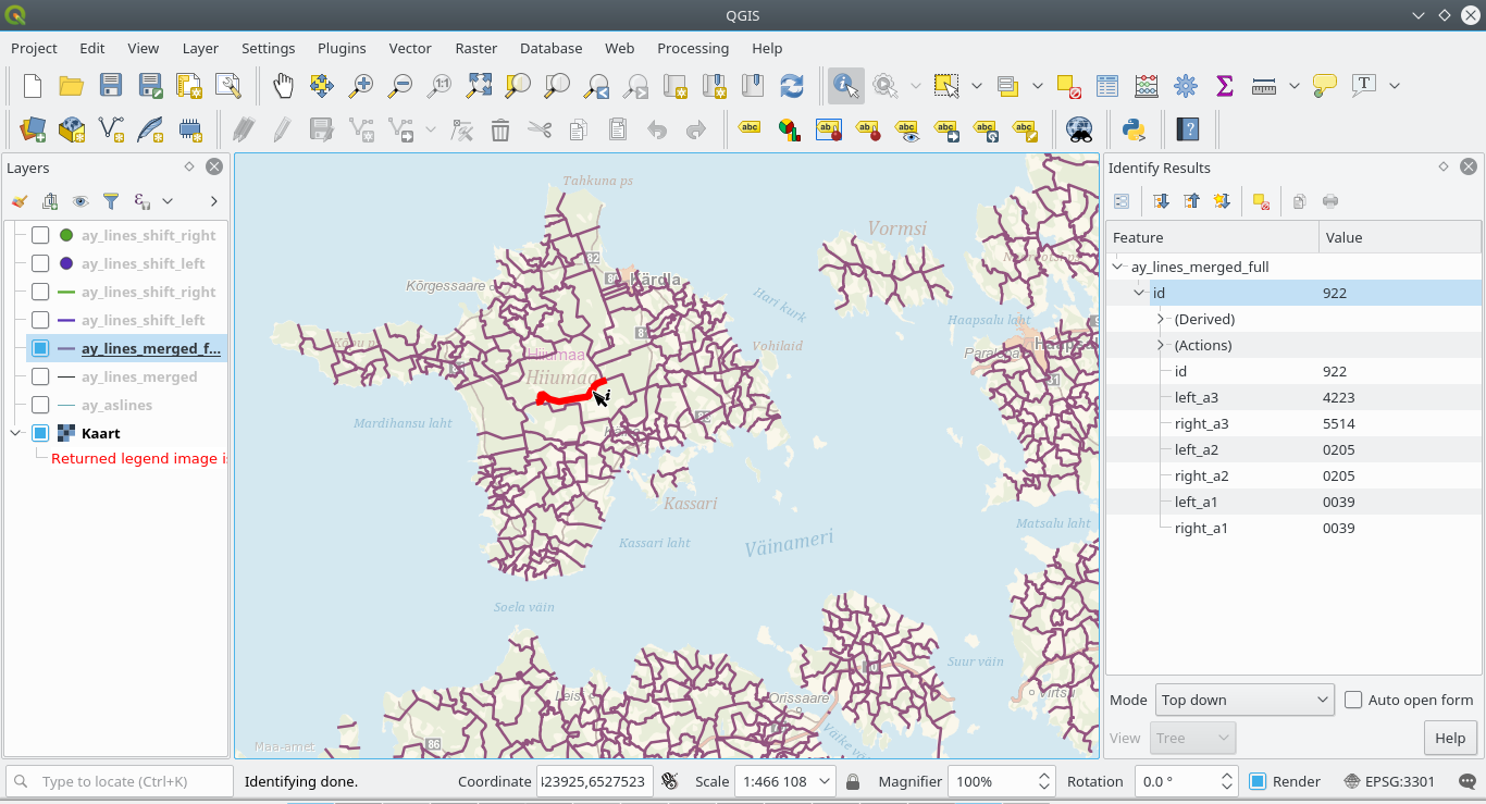
where mk.akood = ay_lines_merged_full.right_a3;And finally we have a set of meshed up polygons with sidedness information.
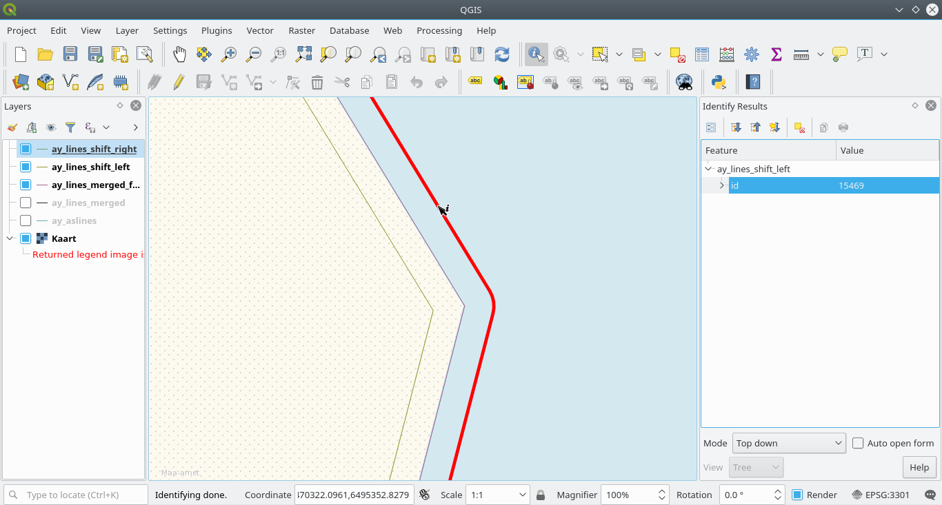
Here’s a closer screenshot of how it all looks in 1:1 scale (remember the
ridiculously small distance that was used for offsets).
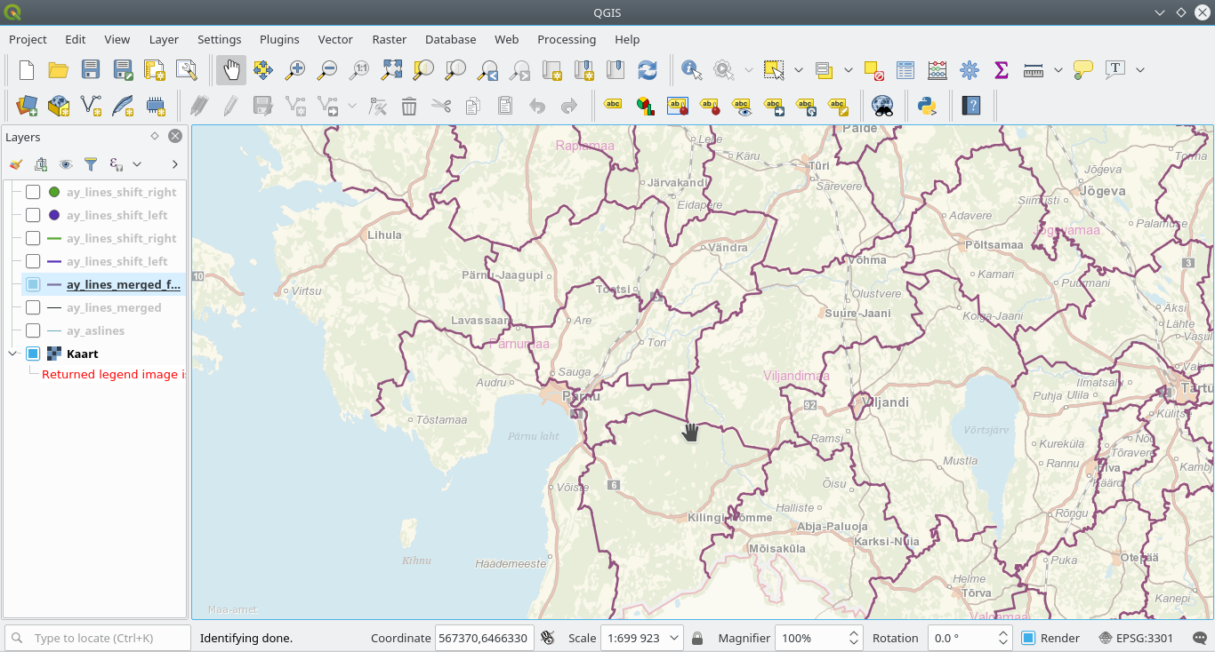
And that’s it. So now for example, if we needed all the borders in between A3 level units but no coastline then a simple filter like
left_a3 is not null and right_a3 is not nullwill produce a layer like:
And if A2 level unit borders are needed the same way, we can simply issue another filter
left_a2 is not null and right_a2 is not null and left_a2 != right_a2resulting in
just remember that the linestrings here for A2 are still per neighboring A3 units. To get them per neighboring A2 units simply merge them.
All-in-alls…
If you ever stumbled upon this writeup and made it here then thank you for bearing till the end. I hope this was helpful (if help was what you were looking for :)). There are other ways of achieving the same result but this worked for me just fine. This writeup is licensed under CC-BY 4.0: Tõnis Kärdi (LonLat OÜ). Except for the SQL code which is licensed under the Unlicense, and is available as a gist here .
If you have any further questions or comments then please feel free to drop me a note.