Developing the body plan and checking with diagonals
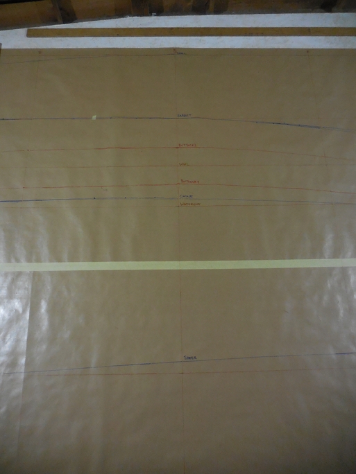
With all the offsets table measurements depleted in the profile view and half-breadth it’s time to move on to the body plan. The lofting grid for the body plan consists of datum and waterlines at the same spacing as in the profile view and a centerline, and buttock lines at the same spacing as in the half-breadth view. As the name suggests the centerline is in the center ( marking the vertical center of the keel/boat) and perpendicular to the datum. Buttocks are placed two to the left from the centerline (for the aft view) and two to the right (for the fore view) with B1 being closer to the centerline and B2 further out.
Now, on every station three locations need to be picked up:
- rabbet - hull bottom meets the keel
- chine - hull bottom and hull side meet
- sheer - hull side meets the deck
We’ll get away with only these three only because there’s no vertical curvature in the hull’s shape so for all frames rabbet to chine is a straight line and chine to sheer is a straight line for all frames except for station #1 but we have a specific measurement for laying down that curve.
For every one of these locations two separate measurements are needed, one from the half-breadth (imagine this as the body plan x-axis value) and one from the profile view (body plan y-axis value). In order to transfer these measurements from profile and half-breadth so-called tick-sticks can be used.
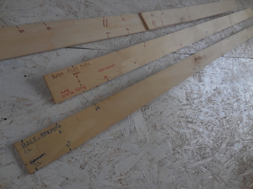
In order not to have to roll my plans open-closed all the time I decided to take as many measurements from other views in one go and mark them distinctly e.g R2, CH2, SH2 for rabbet, chine and sheer at station #2, though having different sticks for profile and half-breadth views.
Essentially the process was to:
- take the measurements (including a mark for datum as a reference) from the profile and transfer these ticks to the body plan CL and B2 body plan grid lines keeping an eye on the marked datum reference. Tick the locations on the verticals and label these because two minutes later you will not remember what in the world were you doing and what are those ticks for.
- take the measurements (incl a mark for CL as a reference) from the half-breadth for the same station and then use a straight edge batten for connecting the measurement ticks taken from the profile and transfer the half-breadth ticks to the body plan keeping an eye on the marked CL reference.
This should be done for all stations.
When this is completed the next step is to draw the waterlines based on the body-plan to the half-breadth view, and buttocks based on half-breadth and body-plan to profile.
For waterlines to the half-breadth we’ll need tick for every station in the body plan for the distance from the centerline at a right angle to the location of the intesection of that waterline and that station. As the centerline is perpendicular to the waterlines then it’s easy to achieve by simply measuring along the specific waterline. These measurements are then transferred to the half-breadth. Waterline ends in the aft and in the fore can be determined using the same set of techniques described in the previous post for determining chine and sheer ends in the aft/fore using measurements from the profile view at the waterline’s intersection with two neighboring station lines as a reference. Faired curves should then be drawn using the already described method of nails and a long batten.
Next up is transferring buttock lines to the profile view.
As before - buttock and station line intersection points are picked up on the tick-stick from the body plan and then - relative to the datum - transferred to the profile view. Both buttock lines intersect the sheer in the fore, but in the aft (because of the way they were measured initially) B2 ends at the intersection of transom and sheer (as a side note: this also was not most probably the wisest of choices… but we’ll see), and B1 somewhere along the transom profile. Simply tick the location on station #9 and station #8 - then using a straight-edge batten where the line intersects the transom, that’s where the B1 ends.
And a again nails, batten and draw a fair curve.
With the buttock lines transferred to the profile it’s time to check up on the work so far. Using a tick stick on every station line on the profile view:
- pick up - relative to the datum - both buttock intersections (B1 and B2) and take them to the body plan
- in the body plan place the tick stick on the respective buttock line and datum
and check if the station shape intersects in the exact same location.
If yes then everything is ok with that station. But if not then
- correct the shape of the station line based on the measurements from the tick stick.
- …aaaand if you re-faired a station line in the last step in the body plan that means that the waterlines in the half-breadth will have to be re-drawn aswell. But don’t do it until all profile-to-body-plan checks have been done.
Luckily - I guess because of the shape of the hull - I did not have to do any re-fairing of station lines in the body plan and could simply get on to drawing the diagonals to the body plan.
In the book “Lofting a Boat: a Step-by-step Manual”, Roger Kopanycia writes:
Once plotted and faired, Diagonals are used to correct any final discrepancies in the Body Plan. They’re generally considered to be the most accurate lines because ideally they are drawn square to the Body Plan curve, almost as if they’re following the line of the planking. In practice this is not possible, as all of the Stations have different curves, so a ‘best-fit’ line is drawn.
As the station lines for this boat are not curved, I decided to go with two pairs diagonals, placing them so that one would pass through the rabbet-to-chine (D1) and the other chine-to-sheer (D2) portions of the station lines. Both of the diagonal pairs intersect the body plan centerline in the same location, although this intersection location is arbitrary (and based on the shipwright’s best knowledge and experience). The most important thing is that a pair of diagonals (to the fore side and to the aft side of body plan) should start in the same location and have the same angle from the centerline.
The diagonal(s' curves) should be plotted just underneath the half-breadth view centerline but as already mentioned on numerous occasions before - free space is a problem so instead I plotted these on top of half-breadth lines using a different color pen.
Using yet another tick-stick, place it on one of the diagonals and mark the intersection of the body plan’s centerline and the location of all station lines that it passes, for both, fore and aft sides of the body plan. Then transfer these to (in my case) the half-breadth view using the centerline as a reference and mark the positions of diagonal-to-station-line intersection points on all stations. Similar to the sheer-to-half-breadth and chine-to-half-breadth (check previous post) the locations of diagonals intersecting the rabbetline in the fore and transom in the aft are picked up from other views.
For the rabbet:
- placing the tick-stick along the rabbetline in the pody plan, tick the location to your stick where the diagonal intersects the rabbet (the height of intersection) in the body plan using datum as the reference
- transfer this mark (the height of intersection) to the profile view stations #0 and #1
- in the profile using station #0 as a reference mark the point of intersection for this line and the rabbetline (distance of intersection) on the tick-stick
- transfer this mark (distance of intersection) to the diagonals' plot and mark it on the centerline and B1 (or B2)
- place the first step’s (height of intersection) tick with reference to the centerline to this line and mark the location on the diagonals drawing. This is were the diagonal ends in the fore.
for the transom:
- using a set square between waterlines and buttocks/centerline using datum as the reference tick the location on the tick stick where the diagonal intersects the transom (the height of intersection).
- transfer this mark (the height of intersection) to the profile view stations #9 and #8
- in the profile using station #9 as a reference mark the point of intersection for this line and the transom (distance of intersection) on the tick-stick
- transfer this mark (distance of intersection) to the diagonals' plot and mark it on the centerline and B1 (or B2)
- place the first step’s (height of intersection) tick with reference to the centerline to this line and mark the location on the diagonals drawing. This is were the diagonal ends in the aft.
Repeat the same procedure for all the remaining diagonals if any. When done then bang your nails and draw a curve with a batten to see if it passes through all the marked positions. If it does then we can assume that the rest of the lines are correct. If all the measured locations are not on the curve then corrections to the body-plan, half-breadth and profile are required.
All was good on the first go with the diagonals I had plotted and so I could move on to the next step which is developing the transom and transom fore face.