Lofting grid and so on...
The process of drawing out full sized plans of the boat starts with laying down a lofting grid (basically like gridlines of a local coordinate reference system) for all three main views of the boat discussed previously:
- profile (also called sheerline view)
- half-breadth (also called waterline view), and
- body plan
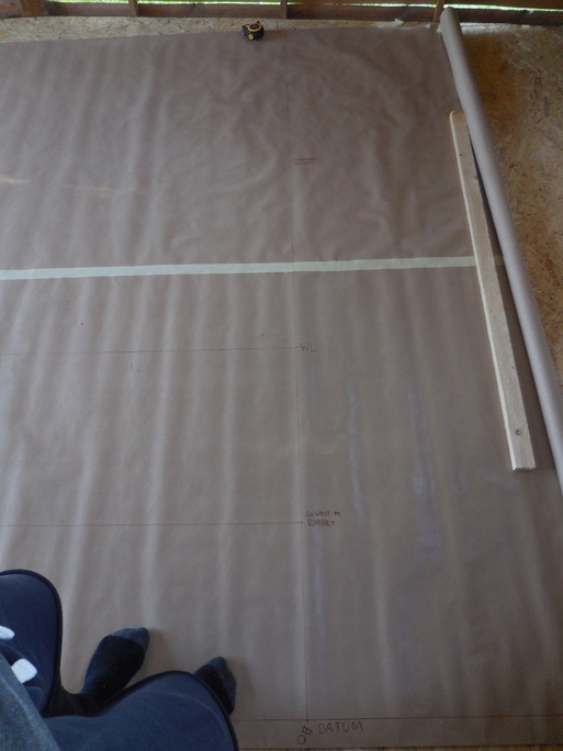
I started with the profile and using my straight edge 2.5m batten drew a straight line at the longer edge of paper. This is the so-called datum and should span at least the length of the boat - edge of transom to the tip of the stem. Ideally with more space available you’d continue the datum line forward of the stem to serve also as a datum (or 0-height reference) for the body plan. But for me that was going to be on another sheet of paper.
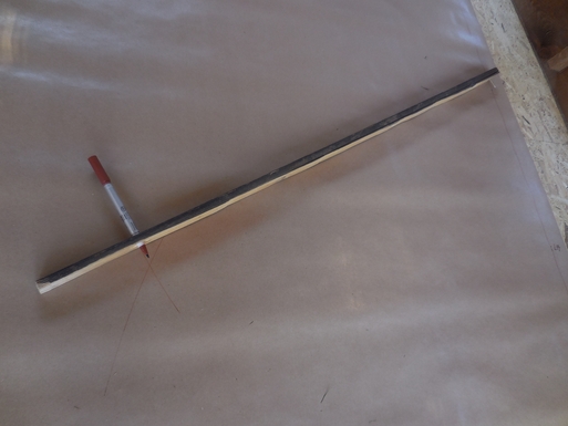
Next up is marking the station lines which will be at 90 degree angles from the datum at a width that the offsets table tells you the boat’s frames will be at - for the boat I’m building it means 10 station lines with #9 at the very end of the transom and then equally spaced towards the fore at a space of 30 inches (76.2 cm) except the very last width between stations #1 and #0 (the fore tip of the stem) at 45 inches (114.3cm). Plotting out these at right angles in reference to the datum line is a bit tricky because already small discrepancies near the datum might cause real problems at the sheerline height (around 1.60-1.70+ m for this boat). So you can’t really use your child’s school protractor for this. One option here is to get yourself a large drawing compass, or you can build a trammel. I opted for the second option: get a straight-edged stick (arbitrary length but mine was abt 1m) and bore two holes in it - one at about 20-30 cm from one edge and another one at the very edge of the other end. The holes should be just about the size of the pen you’re using so if you put it into one of the holes it doesn’t come out very easily. Then put a nail or a screw through near the end of the stick of the 20-30cm hole.
Using this is fairly easy (and I know there’s a name for this method but I really can’t recall it): place your pen in the bored hole that’s closer to the nail, place the nail at the measured station distance on the datum and draw two small ticks intersecting the datum at either side of the measured station location. These must be drawn with the nail in the exact same spot. Then pull your pen out and put it in the hole further back, place the nail on one of the datum and previously ticked line intersection locations and draw a small arc at the approximate location of the perpendicular. Repeat this process also for the other tick you did on the datum.
Now you have two points that you can use your straight edge batten on to draw a line for the station perpendicular to the datum line. Just to be on the safe side (because on paper) I proof-measured the width between the perpendiculars on the other end as well to be the same as they are on the datum before laying down the station line full-size. Ideally, with more space available you’d continue these lines well below the datum line where the half-breadth view should be at. But as with the body plan, I’ll use a separate roll of paper for that.
With the station lines done the next move is to draw waterlines (WL) according to offsets from the boat’s plan. Waterlines are perpendicular to the station lines and parallel to the datum. Unfortunately the offsets I’m using included only the the real waterline height so I added two more arbitrary lines - at the lowest point of rabbet (where the boat’s hull meets the keel) and at transom height. Although at hindsight these lines are essentially quite useless for developing the body plan - the first one, lowest point rabbet will only intersect the keel and a few station lines in a minuscule fashion. The second one (transom height) is a bit better but only for the body plan fore view. In the aft view it only intersects - surprise, surprise - the transom. So later on I added another one, calling it WWL (for whateverwaterline) at a half distance between the waterline and lowest point rabbet. Maybe should have used one more above the waterline also but since the boat’s hull is V-shaped not curved (except for station #1) the frame sides will actually be straight lines and I’ll try not to worry about that too much.
Anyway, having measured and marked the WL locations on station #9, took the batten and transferred the locations as accurately as I could to it using the datum line as a reference and then simply ticked every station line with these same locations from the batten. After which these could be joined together with a straight-edge. Caution here is also to not simply connect dots but use some distance of the line you have already laid out before as a reference as well which should give the idea if the marked locations on station lines are correct or your line is not going at an angle you want it to go.

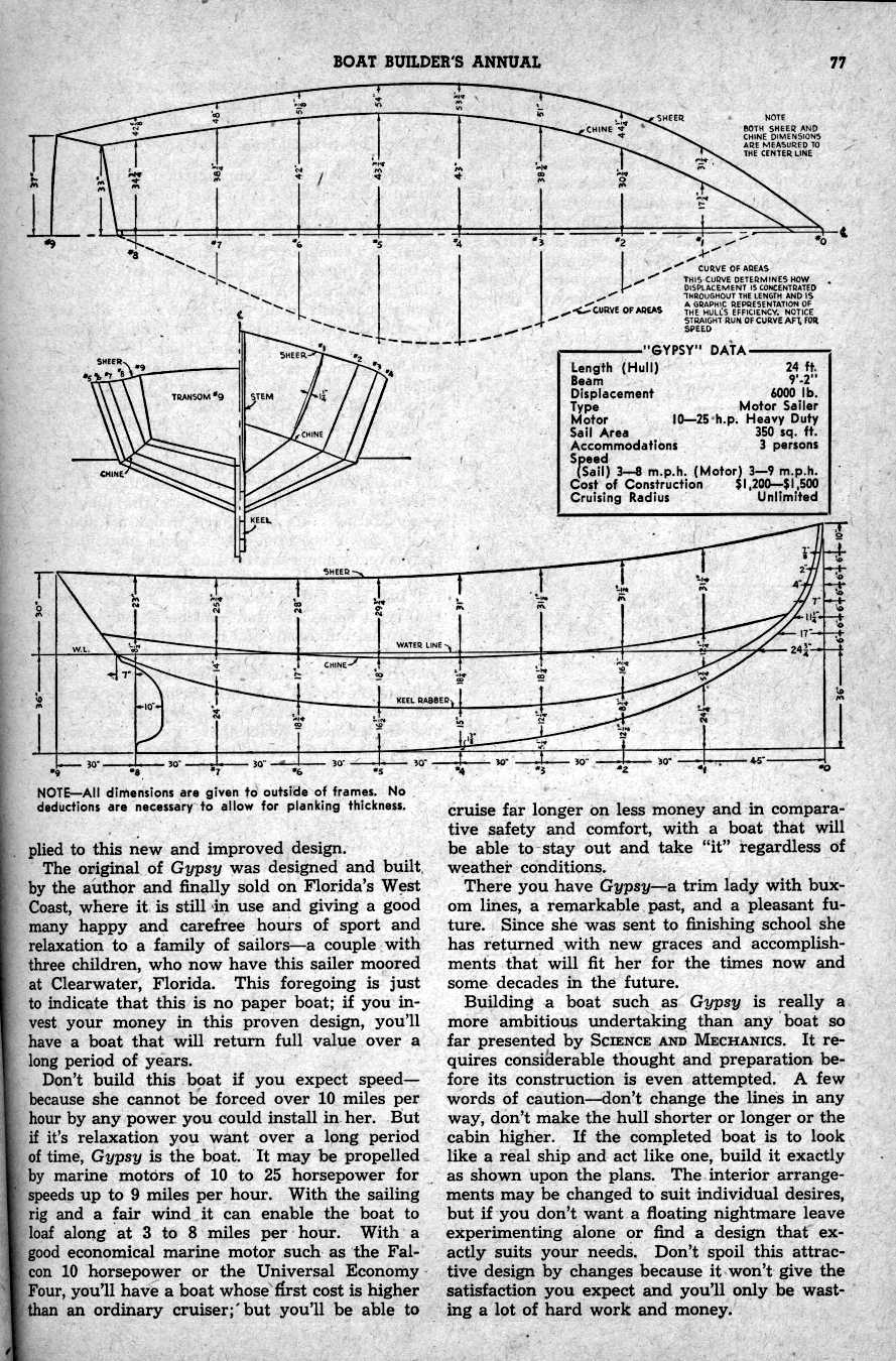
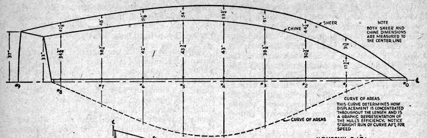
Next up is measuring out the locations of keel, the rabbet, chine and sheer from the datum using a ruler and the measures given in the offsets table on every station.
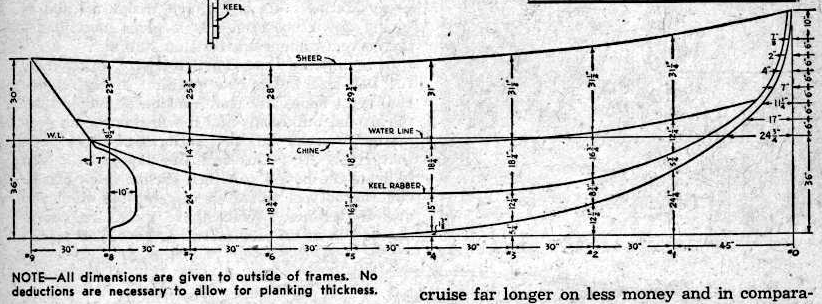
As the original plans from Svensons free boat plans were in imperial units I converted all of them to metric beforehand.
And now there’s not much left to do but to connect all the dots. The only issue here is that the only straight lines in the profile view are the transom profile in the aft and keel from station #8 towards fore to station #5. Everything else is curved.
Starting with the keel curve I drew nails through the paper into the floor at the measured offset points for the keel - not only the curved section but also station #6 (although the keel between stations #6 and #5 is a straight line it will give a nicer curve for the fore stations). Had I had more space I would have used the whole keel profile length. Then took out the plywood laminated long batten pushed it against the nails and fixed both ends with clamps. All of the marked locations laid nicely on the curve so there was nothing else left to do but to draw a curve.
The same was done for all other profile curves: sheer, chine and rabbetline. One word of advice here though. The nails to be used here should have as small a head as possible, the best would be to cut their heads off altogether. Otherwise they will keep the batten away from the marked location by a radius of the nail head size. That’s something I learned on the go…
As you could see in the original profile view there was no height of rabbetline given for station #8. So instead of trying to guess or calculate the exact location I drew the sheerline curve first and then measured down the chine location and rabbetline location to be used for developing chine and rabbetline curves in profile.
With the main lines for profile laid down from the offsets table it’s time to lay down the grid for half-breadth view (unless it wasn’t already done) and draw up the same set of lines according to the offsets table as if looking at half of the boat from above.
The half-breadth lofting grid is connected to the profile view lofting grid through the location of station lines. In addition it has a centerline (CL) which is to be the center of the keel and a few (I guess the number depending on the complexity of hull) buttock lines (B1, B2, …) parallel to the centerline. All these grid lines from half-breadth relate to the body plan (which in turn relates to the profile view through waterlines).
As there’s no mention on the exact sizes of these (as in distance between them) I decided to go with the logic that in order to use the buttock lines efficiently for every station they should intersect at least the frame’s bottom line and side line (because the hull is V-shaped). Which turned into B1 measured at 47 cm from the centerline and B2 twice of that, effectively making B2 intersect the upper side corner of transom.
Having set up the grid, the same procedure follows as with the profile view - you measure and mark distances from the centerline at every station for rabbetline (which in this boat’s case is the half-witdh of the keel), chine and sheer. Then nails, bend your batten and connect the dots. Some special care is needed with the chine location on the stem (somewhere between stations #1 and #0) and on the transom (somewhere between stations #9 and #8) and sheer location on the stem close to station #0 (where sheerline meets the rabbetline). But luckily we have that information available already in the profile view.
Essentially this procedure consists of taking a measurement of the intersection point in the profile view relative to two neighboring station lines between which the location should be and then using these same two station lines for transferring this measurement to the half-breadth view. So:
-
the sheerline meets the keel/rabbetline in the half-breath view between stations #0 and #1 at the same distance where sheerline meets the rabbetline in the profile view between stations #0 and #1. Transfer that measurement from the profile to the half-breadth and find the location where this measurement intersects the rabbetline.
-
the chine meets the keel/rabbetline in the half-breadth view between stations #0 and #1 at the same distance where chine meets the rabbetline in the profile view between stations #0 and #1. Transfer that measurement from the profile to the half-breadth and find the location where this measurement intersects the rabbetline.
-
the chine meets the transom in the half-breadth view between stations #8 and #9 at the same distance where chine meets the transom in the profile view between stations #8 and #9. And the distance for this point from the centerline is given in the offsets table.
In this case of a raked transom the sheerline ends on station #9 and a measurement is given in the offsets table. If it didn’t (e.g. reverse transom) the same set of techiques can be used to locate it’s precise location in half-breadth.
And to finish up - again - nails, batten, check curve, draw line.
Now I have depleted all of the measurement given in the offsets table so from now on all the measurements will be taken from either the profile view or half-breadths to draw up a body plan which is up next.